
Timing in CBRS and Private LTE/5G Networks
The challenges and how to practically overcome them
Executive summary
Citizens Broadband Radio Services (CBRS) will very soon be launching to commercial production deployments. Numerous pilots and PoCs have been successfully conducted by many players in the market. The ecosystem, created by the CBRS Alliance, is as close as possible to maturity.
Overall, CBRS seems good to go. However, history teaches us that when things are scaling up, some overlooked aspects of the technology start raising their heads. Timing is a classic case for that: it is never within focus, there is typically limited knowledge and expertise for it in the organization and the problems it can create are not necessarily of the binary sort (working or not-working).
This paper sheds some light on Timing in CBRS environments and how to mitigate the challenges it poses.
Background
Private LTE and CBRS
The emergence of Private cellular (LTE/5G) networks in general, and CBRS in particular, is one of the latest exciting developments in mobile communications, essentially brining traditional Telco-oriented mobile technologies and services into the enterprise environment and branching into numerous applications.
While these applications are promising and technology is mostly ready for prime time, there is one aspect of actual deployments that may remain elusive in many cases. When networks start ramping up in both scale and variety of scenarios, technically appropriate switching/routing local network equipment may become critical to achieve reliable and stable service.
Timing
There is a requirement to keep all eNodeBs (CBSDs) synchronized to one another and to a local GPS/GNSS based timing source, which in turn will also keep them properly phase synchronized with the outside world, hence assuring operation that does not interfere with neighboring networks, and enabling handovers to the macro-cell mobile network (owned by the mobile operators).
Typical numbers in LTE environments refer to 3usec inter-cell phase alignment. This would require each eNodeB to be within 1.5usec from the timing source.
This paper provides some guidance to the delivery of Timing to the CBSDs in a reliable manner, covering both the Timing source, as well as the requirements of the delivery (backhaul) network.
Assumptions
This article was drafted with the following working assumptions in mind:
- GPS reception is unavailable or unreliable. For example, in indoor environments or urban canyons, GPS signal may not be available at an adequate level.
- The eNodeBs deployed in the network support PTP (IEEE1588) as a timing source, with a reasonable PTP slave implementation (one that can handle some PDV).
- There are wired connections (fiber or Copper) between the eNodeBs and the Timing source element.
- All connections are Ethernet based (in the range of 100M to 10G), i.e. no DSL, GPON, etc., links are used
Timing delivery
The common method
When GPS (and GNSS in general) signals are not adequately available to each CBSD, timing must be delivered over the network. The primary standard method for accomplishing this task is with the IEEE1588v2 standard, aka Precision Time Protocol (PTP).
While other methods are theoretically possible (e.g. NTP), they are not suitable in practice, due to lack of performance, accuracy and suitable network elements.
Source: PTP Grandmaster
A PTP Grandmaster (GM) is the source of timing in the network. It embeds a GPS (GNSS) receiver (this is still the most effective way to keep in sync with the outside world), the necessary protocol building blocks, PTP packet generator and responder, high accuracy timestamping unit, adequate algorithms and oscillator, and the ability to fanout the PTP packets to multiple physical ports of various operating modes (electrical and optical) supporting common networking speeds (100M,1G, 2.5G 10G).
The GM communicates with the PTP slave function in the CBSDs and sends periodic Sync packets. The slaves in turn send Delay Request messages, to which the GM responds with Delay Responses. Using the timestamping information in these packets, the slave recovers the time and clock.
Key GM aspects
There are 3 key aspects essential to evaluate a GM’s suitability:
- Accuracy: indicates the timestamp accuracy of PTP packets coming out of the GM, related to UTC. A good GM should be at least compliant with PRTC requirements (defined in G.8272)
- Slave capacity: the number of slaves that can be supported, typically in Unicast mode and at full packet rate (128PPS). This is not only a technology question, but rather an operational and commercial one
- Supported modes: allowed transport layer (L2 or UDP), forwarding mode (Unicast or Multicast) and step (1 or 2)
Key issues
When discussing PTP based timing delivery, there are two key issues that affect the ability to adequately recover the time at the slave side (i.e. CBSD):
- Delay variation – indicates the amount of variation in latency of packets forwarded through the network. aka Packet Delay Variation (PDV)
- Asymmetry – indicates the difference in latency between the forward and reverse paths (i.e. from master to slave and vice versa)
Both of the above are mostly caused by the network element’s forwarding engine, queuing and scheduling functions.
PDV can be mitigated to a certain degree, by proper QoS configuration in the network and appropriate filtering and servo algorithms at the slave.
Asymmetry, however, cannot be compensated for in a timing unaware network.
Timing distribution
While having a suitable GM is essential for a successful CBRS deployment, without also having a proper distribution network, timing will degrade as PTP packets pass through each node along the path from GM to CBSD. This was not a major consideration when we were only looking at frequency sync (i.e. FDD-LTE), but when phase sync is needed (i.e. TDD-LTE/5G) the challenge is completely different.
In large scale mobile networks, some operators would go as far as building dedicated overlay timing networks. The timing accuracy numbers they have their sights on can get as low as 130nsec accuracy with respect to GPS/GNSS at the eNodeB (having 5G and fronthaul in mind). This is clearly not feasible for a CBRS network, where timing distribution must co-exist with the user data forwarding nodes (i.e. switches and routers).
The typical accuracy goal at the CBSD is 1.5usec, which defines our Time Error (TE) budget. Meeting this budget with legacy networking equipment nodes is a real challenge. Assuming not all nodes (or even none of them) are PTP aware, use of intermediate Boundary Clocks at strategic points may be required (which would help with the lowering overall PDV, but will help very little with path asymmetry). When the situation is too challenging, with still inadequate performance, additional local GMs may be needed. These could be of smaller scale and a more modest port configuration.
Another important aspect of timing distribution is packet loss. Excessive loss of packets will result in unstable performance and loss of lock at the CBSD (which in turn may take it out of service). Good network design and configuration (e.g. with QoS) will minimize this effect.
Figures 1 and 2 illustrate the effect of the network on overall TE, via PDV and asymmetry, in the cases of PTP unaware and PTP aware nodes (i.e. TC or BC; details in following sections).

Figure 1 – PDV and asymmetry, PTP unaware network
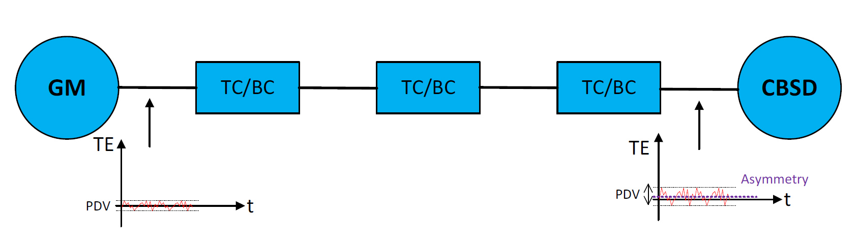
Figure 2 – PDV and asymmetry, PTP aware network
SyncE
Synchronous Ethernet (G.8262) is the packet world’s equivalent of SONET/SDH synchronization. It is based on the line recovered clock. The upside of this method is its simplicity of operation and immunity to traffic conditions. However, SyncE can only be used to deliver frequency, while LTE and 5G networks require phase sync.
Therefore, SyncE on its own cannot provide the necessary functionality, but it can be used in conjunction with PTP and improve overall performance, reliability and resilience of the network (e.g. it can be used for holdover when PTP is down).
Redundancy
Some applications (e.g. public safety, industrial) mandate no single point of failure in their network. When CBRS is the communication method, this would also imply timing cannot have a single point of failure. While the CBSDs would typically have some internal holdover capability that may last for a short period of time (could be as low as a few minutes), a redundant solution cannot be based on the CBSD, but rather on the GM and network side.
Deploying two (or more) GMs, in a geo-diverse manner, would support such a requirement. The GMs should be deployed and configured in a mutually redundant design, so that CBSDs are preferably not aware of any issues, e.g. GNSS antenna failure (the more common failure scenario).
Local transport network
Greenfield vs. Brownfield
Greenfield deployments are always easier to design, as they allow selection of the right components and architecting the network in the optimal way at the time of the build, while keeping in mind future changes and scalability.
However, in a large percentage of the cases, the CBRS services need to be deployed in brownfield environments, overlaid on top of an existing network infrastructure. Such cases would require a careful review of the existing network, measuring of path PDV and asymmetry in various locations and finally designing the timing architecture to fit both the physical layout of the network as well as the timing needs of the CBSDs.
General architecture
- Star: classic and simple fanout deign but lacks protection
- Ring: provides inherent protection but increases the hop count
- Daisy chain: can be effective in buildings (as a backbone) but increases hop count
- Typically, the network will be a combination of a ring or daisy chain as backbone, with a star to fanout from each of the ring/chain nodes. This would imply that network should be either timing aware, or additional GMs should be used (depending on scale).
Intermediate nodes
These are the network elements connecting the CBSDs to the GM as well as the outside world (typically via an Internet gateway). They can either be switches or routers. Deciding on which type to use depends on many factors, and in most cases, it will be a mix of the two.
Either way, the network’s nodes role in carrying timing packets reliably is critical, as explained in earlier sections.
CBRS Grade nodes
A network node that is being used in a CBRS deployment should have the characteristics listed below. We can use the terms CBRS Grade Switch (CGS) and CBRS Grade Router (CGR) to indicate nodes that comply with these requirements.
|
Characteristic |
Description |
|
Security |
Secured and controlled management access; ACLs for data plane |
|
Quality of Service |
Prioritize timing, management and control packets |
|
Carrier Grade |
High reliability, extensive management features (for easy integration) |
|
Timing aware |
PTP aware, preferably with SyncE support |
|
Low latency |
in the range of a few microseconds (typical should be <5usec) |
|
High capacity |
High speed interfaces (1G and up), full wire speed forwarding |
Table 1 – CGS/CGR characteristics
Hop count
From a timing perspective, every node on the network through which PTP packets flow would introduce a certain Time Error. High performance PTP aware nodes would introduce low TE and therefore can allow for a larger hop count (practically making timing a non issue). Unaware nodes, however, may introduce large TE values to a degree that even 2-3 hops would render timing quality useless to the CBSD.
Redundancy
The level of a network’s resilience is always a question of costs vs the application’s reliability requirements. Redundancy can be achieved on a node level, link/path level or both. It is normally recommended to have the network’s core or backbone designed in a redundant manner, with the basic architecture being based on ring topology. This can naturally be extended (at a price of complexity and deployment costs), depending on scale and how critical the communication service is. Figure 3 below shows a typical reference CBRS network architecture.

Figure 3 – reference CBRS network
Practical guidelines
The following guidelines and recommendations address mostly the timing aspect of the CBRS network design. However, they do take into account the network and forwarding plane, as these are tightly related to PTP based timing in such environments.
Network architecture
As mentioned above in General architecture section
Number of hops
As long as the intermediate nodes in the network are Timing aware and exhibit good performance as TCs or BCs, we can go for quite a few hops. For example, a class C capable TC would introduce a cTE of less than 10nsec. A transport chain of 10 hops will introduce an asymmetry of 200nsec at the CBSD, in worst case (considering 100nsec for the GM).
However, if the network nodes are unaware, even a few hops (may be as little as 2-3) may exceed the TE budget and create timing issues. In this case the general rule would be keep hop count to the absolute minimum possible.
Grandmaster selection
A high performance, telecom grade GM is of high importance for stable operation of the CBSDs. It is highly recommended to select a GM that not only has the right capacity and accuracy, but can also support various modes of operation, to ensure quick and simple interop with different PTP slave implementations on CBSDs from different vendors.
The following table provides key parameters for selecting a GM.
|
Requirement |
Must |
Desirable |
|
Port configuration |
Gigabit Ethernet, Electrical Minimum 2 ports |
FE/GE electrical and optical, 10GE optical, Minimum 6 ports |
|
Transport layer |
UDP |
UDP and Ethernet |
|
Forwarding mode |
Unicast |
Unicast and Multicast |
|
Steps supported |
1-step |
1 and 2-step |
|
Minimum supported packet rate (Sync and Del. Req/Resp) |
64PPS |
128PPS |
|
Slave capacity (@full packet rate) |
>32 |
>128 |
|
Timestamp mechanism |
Hardware |
- |
|
Timestamp accuracy |
<15nsec |
<8nsec |
|
Overall accuracy |
<100nsec |
<50nsec |
|
Sources supported |
GPS/GNSS |
GPS/GNSS, PTP, SyncE |
|
Redundancy |
Power |
Power, timing reference sources |
|
Holdover |
1.5usec: 1.5 hours 3usec: 3 hours |
1.5usec: 3 hours 3usec: 6 hours |
Table 2 – GM key requirements
Network elements
In order to take care of network delay variation and asymmetry, the network elements (switches or routers) should be PTP aware, i.e. Transparent Clocks or Boundary Clocks (defined in G.8273.x). As many operating modes as possible should be supported to allow greatest interop flexibility with GMs and CBSDs.
This however, is not sufficient by itself (i.e. ticking the ‘PTP’ check box). The node’s performance should be carefully examined and should be compliant with Class B at least and preferably C or even D. (See G.8273.x)
The following table provides key parameters for network elements.
|
Requirement |
Must |
Desirable |
|
Node type |
TC or BC |
Both |
|
Transport layer |
UDP |
UDP and Ethernet |
|
Forwarding mode |
Unicast |
Unicast and Multicast |
|
Steps supported |
1-step |
1 and 2-step |
|
Minimum supported packet rate (Sync and Del. Req/Resp) |
32PPS (aware) |
128PPS |
|
Timestamp mechanism |
Hardware |
- |
|
Timestamp accuracy |
<15nsec |
<8nsec |
|
cTE introduced |
<20nsec (class B) |
<10nsec (class C) |
Table 3 – network element key timing requirements
QoS configuration
The following actions should be taken to ensure PTP packet delivery in any case, and to minimize delay variation (in the unaware case):
- Enable priority queues
- Use highest priority (classification and queue) for PTP traffic
- Use strict priority for this queue (scheduling can be SP or hybrid)
It is assumed the switches and routers in use are geared for the task.
Network asymmetry and PDV
This guideline is applicable mostly to PTP unaware networks, or aware with low accuracy. If possible, it is recommended to measure the network asymmetry and PDV between the GM and CBSDs in several areas of the network, shooting for the worst paths (longest in terms of hop count). This should preferably be done under traffic load conditions, to simulate normal network operation.
Measurements can be made using a dedicated test set (that is synchronized to GPS/GNSS), or using another GM acting as a slave, with an ability to show TE between PTP recovered time and GPS/GNSS.
CBRS is not Wifi and ping is not enough…
Remember: the fact that you can ping from the GM to the slave or vice versa, doesn’t mean timing can be properly recovered at the CBSD. It only shows there’s IP connectivity between the two elements. It is possible that the Time Error, asymmetry and delay variation along the path would render PTP packets arriving at the CBSD useless for synchronizing it.
What about 5G and fronthaul?
5th generation small cells would basically have a similar timing challenge as in LTE, but with stricter accuracy requirements. Depending on the type of radio technology used, accuracy numbers can go as low as several hundred nanoseconds. Generally, the same principles and recommendations above would apply here as well, with modified performance targets.
When it comes to Ethernet based fronthaul (or midhaul), the numbers are much tighter, down to 20nsec inter-RU phase alignment required for the most demanding technologies (e.g. Massive MIMO). This affects required performance, but there are additional considerations (e.g. TSN support on fronthaul switching elements), which are not in scope of this document.
 Timing in CBRS networks